September 28, 2025
Introduction
Yesterday, the grader passed the density checks, but today the same stretch is failing. The nuclear gauge and sand cone don’t agree, the proof-roll shows soft spots, and the crew is stuck wondering what went wrong. Compaction failures like these are frustrating, but they usually trace back to a few clear causes: moisture outside the specified tolerance around OMC, a lift that’s too thick, the wrong roller for the soil, or a Proctor curve that no longer matches the material.
This article walks through those causes in the same order an experienced inspector or superintendent would tackle them in the field. You’ll see a simple triage list, a diagnostic workflow, a comparison of field test methods, and a troubleshooting matrix that connects symptoms to practical fixes. The goal is simple: help you diagnose the problem quickly, correct it in sequence, and document acceptance without argument.
A quick note: “stabilized layer” refers to any treated subgrade or base where acceptance follows project test methods and timing.
This guide covers compaction troubleshooting and acceptance checks on compacted, stabilized layers. It does not set acceptance for hydrating binders (e.g., cement/lime) with curing windows—follow the project specification and product method statements for those steps.
Why Compaction Fails in Stabilized Layers
Most density failures aren’t random—they’re the result of conditions or practices you can measure and correct. When tests don’t pass, start with these common causes:
- Moisture: too wet or too dry compared to the project’s specified tolerance around OMC.
- Lift thickness: placed deeper than the roller can compact.
- Compaction effort: too few passes or underpowered equipment.
- Roller mismatch: vibratory smooth-drum or plates for granular, free-draining soils or kneading/impact compactors (padfoot/sheepsfoot, rammers) for cohesive/plastic soils.
- Gradation: fines and aggregates not balanced for interlock.
- Non-representative Proctor curve: the lab curve no longer matches today’s material.
- Testing sequence: checks performed at the wrong point during stabilization.
Think of this as triage. Work through it in order to pinpoint the problem without rework.
To diagnose these failures consistently, you need a shared language. The following key terms appear throughout this workflow and in most project specifications—knowing them upfront prevents confusion in the field.
Key Terms You’ll See
- OMC (Optimum Moisture Content): the moisture level at which soil achieves maximum dry density.
- MDD (Maximum Dry Density): the peak of the Proctor curve.
- Proctor (ASTM D698/D1557): lab methods for determining OMC and MDD.
- Proof-roll: a loaded rolling check that reveals wet or weak areas prior to acceptance.
- ITP (Inspection and Test Plan): written plan for what to test, when, and how to resolve disagreements.
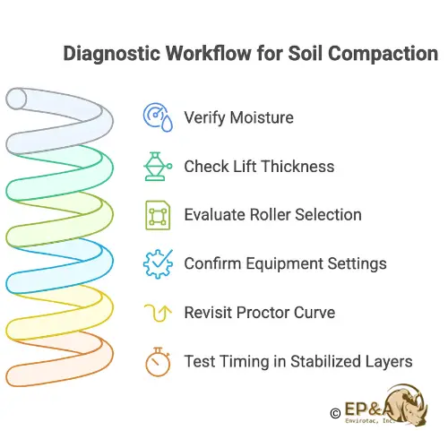
Step-by-Step Diagnostic Workflow
Step 1: Verify Moisture
Moisture is the starting point for every diagnosis. If the soil is outside the specified tolerance around OMC, compaction results will suffer no matter what roller you use.
Nuclear gauge moisture readings can be biased by material and surface conditions; confirm using a reference method such as ASTM D2216 (oven-dry) or ASTM D4944 (calcium-carbide gas pressure), and document any gauge moisture bias per agency procedure. Record both values—this makes disputes easier to resolve later.Moisture check → then act
Compare field moisture to the tolerance band in the project specification.
If outside tolerance: correct moisture first (add water or dry-back). Re-check.
If inside tolerance but density still fails: confirm with ASTM D2216 or ASTM D4944.
If reference agrees and density still fails: move to lift thickness and compactive effort.
Before you record any moisture numbers, make sure today’s gauge setup is documented.
Daily gauge setup (log this):
Standardization/verification completed per agency procedure (date/time; block ID if applicable).
Measurement mode and depth/geometry used.
Surface prep at the test point (seating, smoothing, shielding as required).
Any
moisture bias noted that day (vs. ASTM D2216/D4944) and the value recorded.
Step 2: Check Lift Thickness
Compare the placed thickness to the project specification. Thick lifts don’t compact uniformly.
If too thick, rework in thinner layers.
Tie each reading to Lift # and test depth/geometry used. For through-depth methods, ensure the measurement represents the intended portion of the lift.
If moisture and lift thickness are in bounds and failures persist, the next suspect is how compaction energy is being delivered.
Step 3: Evaluate Roller Selection
Rollers must match soil type:
- Cohesive/plastic soils: kneading compaction with padfoot roller or rammer.
- Granular soils: vibration with smooth drum roller or plate compactor.
- Operator cues: maintain overlap, correct travel speed, and suitable amplitude/frequency.
Step 4: Confirm Equipment Settings
Check roller settings and pass count against both manufacturer guidance and field performance.
Step 5: Revisit the Proctor Curve
If compaction fails despite acceptable moisture and thickness, the Proctor curve may no longer represent the material. Re-run verification using ASTM D698 (Standard Proctor) or ASTM D1557 (Modified Proctor), depending on the specification.
Trigger checklist for re-Proctor/one-point check: any source change, visible shift in gradation/fines, plasticity change noted in field behavior, or persistent test variance after moisture and lift controls are corrected.Once the curve truly represents today’s material, the remaining variable is timing—when and in what order tests are performed.
Step 6: Test Timing in Stabilized Layers
The sequence matters: mix, shape, compact, verify density and moisture, proof-roll,
then apply spray-on surface binders used for dust control. Follow the project’s ITP: perform density/moisture checks and proof-roll before applying binders; if the approved product requires post-spray rolling, note it as a separate step. Always confirm who signs acceptance, what open-to-traffic criteria apply, and under what conditions.Even with the right sequence, some readings will still disagree. When that happens, use a predefined retest path so everyone plays by the same rules.
Retest Protocol
When any reading still fails after Steps 1–6 or when methods disagree, use the retest protocol below so everyone follows the same rulebook.
Retest protocol (use the project’s ITP; pattern shown for clarity):
- Location: offset the retest a small, consistent distance (e.g., along stationing) to avoid testing the exact void.
- Depth/geometry: match the original method’s requirements.
- Count: perform the number of retests the specification calls for; record each as a separate line item.
- Basis for acceptance: Use the reference method identified in the ITP when methods disagree; document the decision path.
Lot/sublot acceptance: If the project uses statistical acceptance (lot/sublot with multiple samples), follow that procedure for the number of tests, locations, and pay factors. This article’s spot checks and retests are in addition to any statistical framework in the specification.
With the retest path set, finish acceptance with one more screen that catches non-uniform support in the field: proof-rolling.
Proof-Rolling: The Last Check
What is a proof-roll? A loaded rolling check is used to reveal wet or weak areas prior to acceptance, performed to the project/agency criterion, and logged with conditions.
Passing density isn’t the end. Proof-rolling confirms that the compacted layer can actually support load. Record the project’s criterion—whether that’s allowable deflection or visual distress—and note the conditions during testing.
Log the setup: equipment make/model, axle load or GVW, tire pressure, coverage/passes, speed, and surface condition. Mark the segment limits and map any distress with stations/offsets. Note the weather and ground temperature.
If proof-rolling fails, treat it as a diagnostic step. Map the weak spots, address moisture or support issues, and retest before moving on. Never apply binders to mask a soft layer; the issue will only resurface.
The diagnostic workflow ends with proof-rolling, but performance in the field depends on more than just passing tests. To keep the layer strong and dust-free over time, stabilization strategies—particularly polymers, complemented by traditional methods—become the next line of defense.
Why Soil Stabilization Polymers Are the Best Choice — and How They Work With Traditional Methods
Among the various options available for soil stabilization, soil stabilization polymers, especially, acrylic polymers stand out because they deliver immediate results, long-term durability, and are safe for the environment. They form a binding matrix around soil particles, cutting dust, preventing raveling, and reducing erosion without harming surrounding vegetation or waterways.
Why polymers excel:
- Immediate effectiveness: rapid effect after application and drying (typically hours), unlike vegetation, which requires establishment.
- Reduced maintenance costs: less watering, grading, and rework.
- Durable performance: withstands traffic and weather extremes.
- Environmentally compatible: Safe alternative to chloride salts or caustic binders (depending on the manufacturer).
- Versatile application: effective across various soil types and climates.
Soil stabilization polymers help reduce watering/grading frequency and improve surface durability when applied at an appropriate rate for site traffic and climate; verify with a test strip.
Traditional methods still matter. Safe, nature-based techniques like vegetation, netting, mulching, and geocells/geogrids all play an important role in stabilizing soil. They:Reinforce slopes and embankments.
Protect soil from long-term erosion.
Provide ecological benefits like habitat and natural dust control once vegetation is established.
Vegetation takes time to grow and doesn’t solve immediate dust challenges.
Geocells and geogrids confine soil but don’t eliminate surface dust.
- Watering is only a short-term measure.
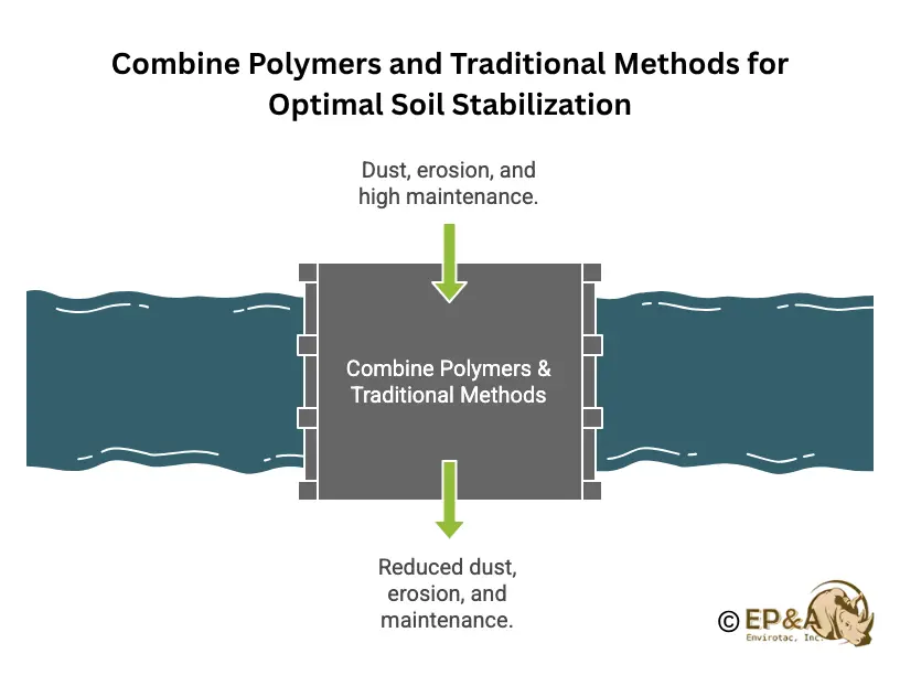
The best approach is combined.
Use polymers for immediate dust control and soil binding.
Pair with vegetation, geocells, or mulching for long-term resilience.
Together, these methods reduce rework, extend surface life, and balance performance with environmental stewardship.
In short, polymers provide the performance edge, and traditional safe methods amplify it over the long run. The two work better in tandem than in isolation.
While strategic choices like polymers and traditional reinforcements shape the long-term stability of a project, the day-to-day reality on site still comes down to diagnosing why a test failed. That’s where a practical reference tool becomes essential. The next section on troubleshooting matrix distills the most common compaction failure patterns into a quick guide for field crews.
Troubleshooting Matrix
Use this matrix during the workflow to narrow causes quickly—and again after proof-rolling if a section still shows distress.
Table: Common compaction failure patterns and corrections.
| Symptom | Likely Cause | Checks | Corrections |
|---|---|---|---|
| Low density + low moisture | Dry soil | Field vs. ASTM D2216/D4944 | Add water, re-compact |
| Low density + high moisture | Wet soil | Field vs. ASTM D2216/D4944 | Aerate/dry, re-compact |
| Low density + correct moisture | Lift too thick/insufficient passes | Thickness measurement, roller log | Rework thinner lifts, adjust effort |
| Inconsistent nuclear readings | Gauge bias | Compare with ASTM D2216/D4944 | Document bias, correct process |
| Density passes, proof-roll fails | Weak support | Visual + mapped distress | Correct moisture/support, retest |
Once you’ve identified the fix, the next step is making it defensible—record what you did, where, and why. Without clear logs, even correct decisions can be disputed.
Logs and Documentation
The fastest way to end disputes is airtight records—use the log formats below to make every decision traceable.
Keep everything traceable: moisture/OMC checks, Proctor source, roller passes, weather, test timing. These become your shield in disputes.
Templates for Field Logs
Moisture/Density Log
| Date | Station/Offset | Lift # | Method | Moisture | Dry Density | Tolerance Band | Result | Test Depth/Geom | Notes |
|---|
Proof-Roll LogSurface Binder Application Log
| Date | Segment | Application Rate | Dilution | Nozzle/Speed | Temp/Weather | Cure/Open Criteria | Notes |
|---|
Field Example Template
Project: [County/City, route/segment]
Soil/material: [e.g., clay subgrade / stabilized base]
Acceptance: [Proctor method + moisture tolerance band]
Issue observed: [e.g., density fails / proof-roll distress]
Checks performed:
Moisture vs tolerance: [value + pass/fail]
Reference method (ASTM D2216 / ASTM D4944): [value]
Lift thickness: [mm/in]
Roller passes/settings: [count/notes]
Proctor curve representative?: [yes/no + action]
Corrections applied: [moisture correction / thinner lift/roller change]
Result: [density pass/fail; proof-roll pass/fail; date/time; signer]
Notes: [weather, temperature, traffic control]
Once a section is accepted, the focus shifts from passing tests to long-term performance—set your surface binder rate with a small, controlled trial.
Trial Section (Test Strip) for Binder Rate
- Select segment: uniform material/traffic exposure; mark limits.
- Pre-conditions: density and proof-roll already accepted; log weather and temperature.
- Prepare surface: light blade if needed; correct moisture to tolerance; re-compact/shape.
- Apply binder: choose two small adjacent lanes with different application rates (Base Rate A vs. Base Rate B); record dilution, nozzle, and travel speed.
- Observe & log: after set times (1 day, 7 days), document dust/ravel condition and any rework needed.
- Select rate: choose the lane that balances performance and practicality; adopt that rate for the main area and note the cure/open-to-traffic criteria.
Observe: visible dust under comparable traffic, raveling at wheel paths, aggregate pick-up on tires, and a need for re-grading. Note conditions at each observation time so comparisons are fair.
Edge Cases Worth Planning For
- Weather/hold points: if rain or temperature pushes moisture outside the tolerance band,pause placement/acceptance, note conditions, and resume only after moisture returns to tolerance and the surface is stable.
- Material variability: high-plasticity clays and recycled bases often need thinner lifts and closer control of roller settings.
- Operations: night shifts and live traffic require clear open-to-traffic criteria and sign-offs in the ITP.
- Drainage: correct ditching and cross-fall before re-compaction or applying any surface binder.
Specification Language That Reduces Disputes
To convert the field rules above into contract language, use the neutral clause below without changing your acceptance criteria.
Surface Binder on Stabilized Layers (Non-Hydrating)
Density and moisture acceptance testing shall occur before any surface binder application.
Proof-rolling shall be performed and passed prior to application; the project/agency criterion used shall be recorded.
Surface binder shall not modify density or moisture acceptance criteria.
Maintenance may include light blading, moisture conditioning, recompaction, shaping, and post-acceptance binder application per the approved method statement.
Record application rate, coverage, ambient conditions, and cure/open criteria in the daily report.
Choosing the Right Soil Stabilization Product
Not all soil stabilization products are created equal — and even the best ones can fail if applied incorrectly. Selecting the right solution depends on soil type, project goals, environmental constraints, and traffic demands.
What can go wrong with the wrong choice:
- Chemical incompatibility: Some soils are incompatible with calcium-based stabilizers (e.g., high-sulfate subgrades can undergo ettringite-related heave; organic-rich soils may not gain strength), so lab checks are essential before specifying lime or cement.
- Environmental impact: Chloride salts can harm vegetation and leach into groundwater.
- Temporary fixes: constant watering or grading controls dust only for a few hours.
Even the right product can fail if…
Manufacturer’s guidelines are ignored (wrong dilution, spray rate, or cure time).
Soil preparation is skipped (binder applied to loose lifts).
Testing is bypassed (no trial sections or proof-rolls).
Weather conditions are overlooked (rain or extreme cold disrupts curing).
Best practices for success:
Start with testing.
Follow the manufacturer’s guidelines.
Prepare the surface properly.
Document and monitor with ITPs.
Why polymers give you more margin for success: Acrylic polymer solutions primarily form a film that binds fines (a physical mechanism), which avoids some soil-chemistry incompatibilities. That makes them more forgiving in variable site conditions — but still dependent on good practices for best results.
FAQ
Q1: Density passed, but proof-roll failed. What now?Treat the proof-roll as triage: map weak zones, check moisture vs the tolerance, and verify with ASTM D2216 or D4944 if needed, correct support or lift thickness, then re-verify per the ITP.
Q2: When should we re-run Proctor?
Any material/source change or repeated inconsistency triggers re-sampling and either a one-point check or a new curve, per the specification.
Q3: Can we re-blade and re-compact a stabilized layer?
Yes—when acceptance is not yet achieved or a maintenance cycle is due. Sequence: light blade → moisture condition → re-compact/shape → verify density and proof-roll → apply surface binder only after acceptance.
Q4: The moisture tolerance in the specification feels too tight for today’s weather. What can we do?
Coordinate with the specifier for a documented approach (e.g., adjusted test frequency, hold points, or retest protocol) rather than over-wetting to chase a number. Record the agreed path in the daily report.
Q5: Standard vs. Modified Proctor—does it matter here?
Use the method named in the project specification (ASTM D698 or ASTM D1557). Do not compare field results to a curve developed with a different Proctor method unless the specification authorizes it.
Conclusion
Compaction failures don’t happen at random—they follow a pattern. By starting with moisture, confirming with ASTM reference methods, checking lift thickness, roller type, and Proctor accuracy, and finishing with proof-rolling, you build both a diagnostic path and a defensible record. That discipline reduces disputes, saves rework, and ensures the stabilized layer performs as designed.
For projects that require durable dust control and long-term performance, consider surface binders and stabilizers that integrate smoothly into this sequence. Acrylic-based soil stabilization polymers are one of the best options when applied after density and proof-roll acceptance—they help lock in the gains you’ve achieved in compaction without interfering with acceptance tests.
Applications - Dust Control & Soil Stabilization Products

Leave a Reply